Build Tips and Addemdums
From Flex Innovations Wiki
NoseWheel Addendum
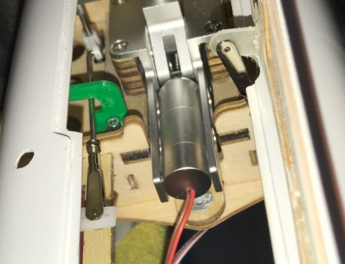
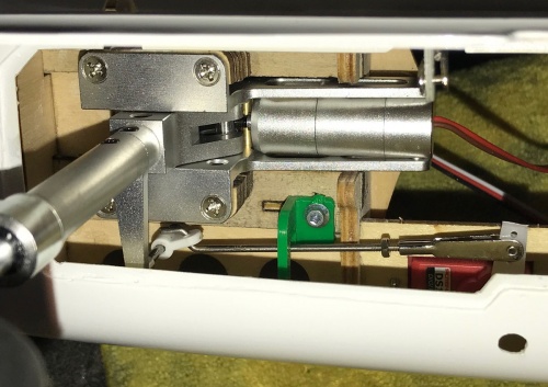
We have made an improvement to the original design to use a 3D printed part (shown in green) to constrain the Nose Wheel Steering Linkage. This technique limits the 'twisting' of the nose strut when it retracts and prevents the possibility of jamming.
For US customers, the part should be located in the accessory box near the vertical fin if you bought only and ARF. If your shipment is in more than one box, the 3D printed part will likely be with your accessories box in a baggy.
Please install the part as shown.
- We suggest adjusting the linkage so the wheel is centered when the servo is centered before beginning.
- Please tighten each of the retract mounting lug screws. The wood can compress over time and with humidity changes.
- Locate the part on as shown in the photos. The fore/aft location of the part does not need to be precise.
- Drill a 1/16" (1.5mm) pilot hole.
- Attach the part with a #2 Sheet Metal Screw or equivalent.
- Test cycle the landing gear, it should not contact the door cutout or twist enough to cause a jam.
Elevator Center Note
Please center the Elevator as noted. The Trailing Edge Top Skin of the Horizontal Flying Stab Should be 1 to 1.5mm above the top surface of the Fairing as shown.


