Difference between revisions of "QQYak54 35cc/Aura"
m (Added Futaba Receivers) |
m |
||
| Line 15: | Line 15: | ||
=== Flight Mode 1: 3D High Airspeed Speed === | === Flight Mode 1: 3D High Airspeed Speed === | ||
| − | * For high speed flying (full throttle) at high | + | * For high speed flying (full throttle) at high rates. Ideal for tumbling, high energy aerobatics. |
* Rate for aileron is 70% while rudder and elevator travelling at max deflection. | * Rate for aileron is 70% while rudder and elevator travelling at max deflection. | ||
| − | * Gains are set low and expo | + | * Gains are set low and expo is set high. |
=== Flight Mode 2: Sport === | === Flight Mode 2: Sport === | ||
| Line 26: | Line 26: | ||
=== Flight Mode 3: 3D Slow Speed === | === Flight Mode 3: 3D Slow Speed === | ||
* Ideal for Harriers, torque roll, hover, waterfall, flat spins. | * Ideal for Harriers, torque roll, hover, waterfall, flat spins. | ||
| − | * | + | * Rates are maximum for all control surface. |
| − | * Gains | + | * Gains are highest. |
| − | ''Note: This mode it is not | + | ''Note: This mode it is not meant for high speed flight. As the gains are at their maximu, high control surface oscillations may occur with may lead to a potential crash.'' |
=== Gyro On/Off === | === Gyro On/Off === | ||
| Line 54: | Line 54: | ||
* The Gear Channel is controlled by a 3 Position Switch, direction can be changed for personal preference. | * The Gear Channel is controlled by a 3 Position Switch, direction can be changed for personal preference. | ||
* Ch7/Aux2 is controlled by a 2 Position Switch, direction can be changed for personal preference. | * Ch7/Aux2 is controlled by a 2 Position Switch, direction can be changed for personal preference. | ||
| − | < | + | <br /> |
| + | [[File:QQYak54_35cc_TransmitterSetup.png|thumb|none|Common Transmitter Settings starting with a freshly reset transmitter and maintaining normal wing and tail types]] | ||
| Line 79: | Line 80: | ||
The QQ Yak 54 35cc and Aura can be used with a traditional PWM Servo Connection from a standard receiver, but it requires Y-Harnessing the Ailerons and loses the capability turn off the gyro during flight or scale gains. | The QQ Yak 54 35cc and Aura can be used with a traditional PWM Servo Connection from a standard receiver, but it requires Y-Harnessing the Ailerons and loses the capability turn off the gyro during flight or scale gains. | ||
| − | ===== Step 4.1.A - Digital Receiver Connections ===== | + | ===== Step 4.1.A - Modern Digital Receiver Connections ===== |
A Digital Connection is Spektrum SRXL, Futaba S.Bus, Graupner Hott SUMD, JR Mode B. A single Male to Male servo extension is connected between the Digital Port on your Receiver and 'Port B' on the Aura as shown below. | A Digital Connection is Spektrum SRXL, Futaba S.Bus, Graupner Hott SUMD, JR Mode B. A single Male to Male servo extension is connected between the Digital Port on your Receiver and 'Port B' on the Aura as shown below. | ||
| − | + | <br /> | |
| + | [[File:QQYak54_35cc_DigitalConnection.png|thumb|none|Modern Digital Receivers transfer all channel data via single Male-to-Male extension from the Receiver to the Aura B Port]] | ||
* For Spektrum SRXL, we suggest receivers such as AR8010T, AR9030T, AR9020, AR12020, or AR12120. <small>''[[Aura/SpektrumUse|See the Spektrum Use Notes for Additional Details]]''</small><br/> | * For Spektrum SRXL, we suggest receivers such as AR8010T, AR9030T, AR9020, AR12020, or AR12120. <small>''[[Aura/SpektrumUse|See the Spektrum Use Notes for Additional Details]]''</small><br/> | ||
| Line 89: | Line 91: | ||
* For JR Mode B receivers. | * For JR Mode B receivers. | ||
| − | + | * If you are using a modern Digital Receiver Connection to Aura (SRXL, S.Bus, Graupner Hott, JR Mode B) | |
| − | + | ||
| − | + | ||
| − | + | ||
| − | + | ||
| − | + | ||
| − | + | ||
| − | * | + | |
** Throttle Servo to Receiver | ** Throttle Servo to Receiver | ||
** L. Aileron Servo to Aura Port S2 | ** L. Aileron Servo to Aura Port S2 | ||
| Line 103: | Line 98: | ||
** L. Elevator Servo to Aura Port S5 | ** L. Elevator Servo to Aura Port S5 | ||
** Rudder Servo to Aura Port S6 | ** Rudder Servo to Aura Port S6 | ||
| − | |||
| − | + | <br /> | |
| + | [[File:transmitterSetup.jpg|thumb|none|Servo Wiring to the Aura and Receiver using a Modern Digital Receiver Connection]] | ||
| + | |||
| + | |||
| + | |||
| + | ===== Step 4.1.B - Traditional PWM Servo Connections ===== | ||
| + | A traditional PWM Servo Connection is made using 4 Male-to-Male Servo extensions from the Receiver to the Aura Ports. | ||
| + | |||
| + | [[File:QQYak54_35cc_PWMConnections.png|thumb|none|Servo Wiring to the Aura and Receiver using a Traditional PWM Servo Connections from the Receiver]] | ||
Make a fancy graphic like the user manual but describe Y Harness. | Make a fancy graphic like the user manual but describe Y Harness. | ||
| Line 112: | Line 114: | ||
Plug in some good batteries. Talk about powering the ignition separately. At least one battery. | Plug in some good batteries. Talk about powering the ignition separately. At least one battery. | ||
| + | <Gallery> | ||
| + | File:transmitterSetup.jpg|thumb|none|Gas Powering | ||
| + | File:transmitterSetup.jpg|thumb|none|Electric Powering | ||
| + | </Gallery> | ||
=== Step 5 - Aura Config Tool Setup === | === Step 5 - Aura Config Tool Setup === | ||
If you haven't installed the Aura Config Tool yet, go here to do that. | If you haven't installed the Aura Config Tool yet, go here to do that. | ||
| − | You must use at least version 1.4.1 of the Aura Config Tool, click here for instructions to check your Aura Config Tool version and update it. | + | You must use at least version 1.1.4.1 of the Aura Config Tool, click here for instructions to check your Aura Config Tool version and update it. |
You must use at Aura Firmware v1.4+ for the Yak 54. Click here for instructions to check your Aura Firmware and how to update the firmware. | You must use at Aura Firmware v1.4+ for the Yak 54. Click here for instructions to check your Aura Firmware and how to update the firmware. | ||
Revision as of 20:31, 21 March 2017
Contents
- 1 QQ Yak 54 35cc with Aura
- 2 QQ Yak 54 35cc Aura Flight Modes
- 3 QQ Yak 54 35cc Aura Install
QQ Yak 54 35cc with Aura
The Aura 8 Advanced Flight Control System (AFCS) is an optional, but highly recommended accessory to your QQ Yak 54 35cc aircraft.
The Aura 8 AFCS is a 3 axis gyro, servo hub and channel expander all rolled into one device. We have developed the Aura 8 to be compatible with all major radio brands. You no longer need to spend a fortune, nor be restricted to specific radio types to experience state of the art control. The Aura 8 is designed to enhance the pilots experience, while not interfering with the pilots control. Your aircraft will fly as if it were bigger, and in less wind, even though it is as agile as you want it to be.
The Aura 8 Open Stock version ships with a blank configuration that can be configured to virtually any fixed wing aircraft. Our team has spent hours fine tuning the settings for the QQ Yak 54 35cc to offer you an exceptional feel of accuracy and control.
The Aura 8 is programmed thru the Aura Config Tool on a PC. You can use the Aura Config Tool "Wizard" to create a new model preconfigured for the QQ Yak 54. Please follow the steps below for the easiest install and best flying experience!
QQ Yak 54 35cc Aura Flight Modes
With the Aura properly configured, the Gear channel changes the Aura's "Flight Mode". Each Flight Mode has specific rates, expos, and gyro settings (gains, stick priority, etc) for different flying styles. The QQ Yak 54 35cc has been configured with the flight modes below. As you fly, you change the Flight Mode for your flying style.
Flight Mode 1: 3D High Airspeed Speed
- For high speed flying (full throttle) at high rates. Ideal for tumbling, high energy aerobatics.
- Rate for aileron is 70% while rudder and elevator travelling at max deflection.
- Gains are set low and expo is set high.
Flight Mode 2: Sport
- For sport or precision aerobatic.
- Rates are low, expo adjusted for smooth flight.
- Gains are low.
Flight Mode 3: 3D Slow Speed
- Ideal for Harriers, torque roll, hover, waterfall, flat spins.
- Rates are maximum for all control surface.
- Gains are highest.
Note: This mode it is not meant for high speed flight. As the gains are at their maximu, high control surface oscillations may occur with may lead to a potential crash.
Gyro On/Off
We have set up Aux2/channel 7 to be your switch to turn on or off the gyro.
QQ Yak 54 35cc Aura Install
Step 1 - Aircraft Setup
Before installing the Aura, confirm you:
- Followed the build instructions in the manual
- Confirm you have the servo arms and pushrods connected as follows:
- Aileron 1.5 in/out from servo center
- Elevator 1.25 in/out from servo center
- Rudder 1.5 out from servo center (double servo arm/each side)
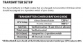
Step 2 - Transmitter Setup
Page 26 of the QQ Yak 54 35cc manual describes how to configure your transmitter.
In general, please make sure the following are set correctly:
- Start with a fresh transmitter model configured for a Normal Wing: 1 Aileron, and Normal Tail Type: 1 Elevator, 1 Rudder.
- Aileron/Elevator/Rudder travels set at 125% (JR Mode B users set travels to 88%)
- Do not change the Aileron/Elevator/Rudder directions from the default normal directions in a fresh transmitter model.
- The Gear Channel is controlled by a 3 Position Switch, direction can be changed for personal preference.
- Ch7/Aux2 is controlled by a 2 Position Switch, direction can be changed for personal preference.
Step 3 - Aura Mounting
Mount the Aura 8 to the airframe using the included double-sided foam tape to the plywood tray. It is also recommended to install a hook and loop strap around the Aura for added protection. It is important to eliminate any tray flex that could cause vibration or servo oscillation issues with your Aura.
For the QQ Yak 54 35cc, you should mount the Aura with the Servo Pins facing Up and the Remote Receiver ports pointing forward toward the Nose. The Aura should be aligned with the axis of the aircraft.
Note: It is not critical to install the Aura on the CG. It is important to minimize any plywood tray flexing.
See the Expanded User Guide for Additional Details
Step 4 - Aura Connections
After mounting the Aura, 3 types of connections must be made to the Aura:
- Receiver Connections
- Servo Connections
- Power Connections
Step 4.1 - Receiver Types/Connections
For the QQ Yak 54 35cc, we recommend using a full-range receiver with a modern Digital Connection rather than traditional PWM Servo Connections. Using a modern digital receiver connection gives the Aura access to precise data of each channel for additional gyro enabled outputs, simplifies wiring, and allows for more advanced features.
The QQ Yak 54 35cc and Aura can be used with a traditional PWM Servo Connection from a standard receiver, but it requires Y-Harnessing the Ailerons and loses the capability turn off the gyro during flight or scale gains.
Step 4.1.A - Modern Digital Receiver Connections
A Digital Connection is Spektrum SRXL, Futaba S.Bus, Graupner Hott SUMD, JR Mode B. A single Male to Male servo extension is connected between the Digital Port on your Receiver and 'Port B' on the Aura as shown below.

- For Spektrum SRXL, we suggest receivers such as AR8010T, AR9030T, AR9020, AR12020, or AR12120. See the Spektrum Use Notes for Additional Details
- For Futaba S.Bus, we have test our own R2008SB (S-FHSS), R6303SB (FASST), and R7008SB (FASSTEST), but expect any any S.Bus receiver to work. See the Futaba Use Notes for Additional Details
- For Graupner Hott SUMD, we have tested GR12L and GR16 receivers. See the Graupner Use Notes for Additional Details
- For JR Mode B receivers.
- If you are using a modern Digital Receiver Connection to Aura (SRXL, S.Bus, Graupner Hott, JR Mode B)
- Throttle Servo to Receiver
- L. Aileron Servo to Aura Port S2
- R. Aileron Servo to Aura Port S3
- L. Elevator Servo to Aura Port S4
- L. Elevator Servo to Aura Port S5
- Rudder Servo to Aura Port S6
Step 4.1.B - Traditional PWM Servo Connections
A traditional PWM Servo Connection is made using 4 Male-to-Male Servo extensions from the Receiver to the Aura Ports.

Make a fancy graphic like the user manual but describe Y Harness.
Step 4.3 - Power Connections
Plug in some good batteries. Talk about powering the ignition separately. At least one battery.
thumb|none|Gas Powering
thumb|none|Electric Powering
Step 5 - Aura Config Tool Setup
If you haven't installed the Aura Config Tool yet, go here to do that.
You must use at least version 1.1.4.1 of the Aura Config Tool, click here for instructions to check your Aura Config Tool version and update it.
You must use at Aura Firmware v1.4+ for the Yak 54. Click here for instructions to check your Aura Firmware and how to update the firmware.
Create the QQ Yak 54 35cc Model
- Go to File and chose “New Aura Config Tool File Wizard”
- Select Aura type “Open Stock” and click Ok.
- Name your aircraft
- Select airframe Type: QQ Yak54 35cc
- Wing type would be selected to 2 aileron servos
- Select your TX
- Select your RX
- Tail will be selected to 2 elevators, 1 rudder
- Save it in your favorite PC Location
Note: Be sure your Aura 8 it is mounted on the plane as shown in the config tool. If any different adjust by clicking on :Adjust Orientation” button.
Step 6 - Aura Config Tool Tuning
Step 6.1 - Center the Control Surfaces
Adjust all control surface to neutral by using Aura sub-trims.
Aura sub-trim can be found by click on “Servo Ports”.
Select the control surface to adjust and adjust sub-trim value as need it.
Step 6.2 - Measuring the Control Surfaces
If servo arms are connected in the correct location as indicated above, and pushrod length as recommended in the airplane manual, all control surface would be travelling at correct deflection. In case of Ailerons, make sure that right and left aileron travel same up a and down (no differential) For both elevator halves also make sure they are travelling equally up and down. If you find differences (most possible) go to “Servo Port” Tab and adjust the respective channel using “Servo Output Scaling”. Note: When you adjust control surface travel make sure there is no binding.
Step 7 - Control Direction and Gyro Direction Testing
Do the tests as described in the manual