Difference between revisions of "FlexJet Pro/TurbineConversion"
| Line 9: | Line 9: | ||
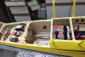
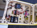
The primary conversion involves installing the turbine mounts and turbine. Installing the tailpipe, Assembling and installing the fuel tanks, and equipping and installing the forward equipment tray. | The primary conversion involves installing the turbine mounts and turbine. Installing the tailpipe, Assembling and installing the fuel tanks, and equipping and installing the forward equipment tray. | ||
| − | Turbine aircraft should be fitted with Wheel Brakes. These are drop in units! | + | Turbine aircraft should be fitted with '''Wheel Brakes'''. [https://www.flexinnovations.com/product/flex-jp-55mm-wheels-brakes-brake-controller/ These are drop in units!] |
'''NOTE:''' that KingTech recommends running the engine outside the model with the assembled equipment tray and fuel system. Flex Innovations used this procedure and had complete success. | '''NOTE:''' that KingTech recommends running the engine outside the model with the assembled equipment tray and fuel system. Flex Innovations used this procedure and had complete success. | ||
Revision as of 18:17, 8 July 2020
Contents
FlexJet Pro Turbine Conversion
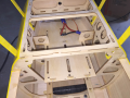
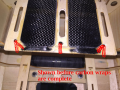
The FlexJet Pro was designed with turbine conversion in mind. The inlet was routed down to provide ample space for a fuel cell. The forward equipment tray was made removable so an alternate could be installed. The Tailcone is removeable to ease component installation.
The FlexJet Pro on a 4.5kg offers and excellent turbine experience. It gives an aerobatic 'fast jet' experience while never feeling heavy. Power is impressive and never lacking.
Flight time can vary depending on fuel tank install and flying style. The K-45 G3 flies about 4:20 with the 24oz main tank, and beyond 5:30 with the 34oz main tank. These times allow for startup, and ample reserves for a go around.
The primary conversion involves installing the turbine mounts and turbine. Installing the tailpipe, Assembling and installing the fuel tanks, and equipping and installing the forward equipment tray.
Turbine aircraft should be fitted with Wheel Brakes. These are drop in units!
NOTE: that KingTech recommends running the engine outside the model with the assembled equipment tray and fuel system. Flex Innovations used this procedure and had complete success.
Turbine Selection
- At the time of this writing, Flex Innovations has tested the KingTech K45 G3 and have found it to be a perfect match.
- The chosen motor uses the same bolt pattern and firewall hole locations as a DA Gas Engine making mounting easy.
- The Prop bolt pattern also matches the DA 4-bolt pattern.
- The Zicoy X45 is very similar, and its mounting was considered in the design. It should be easily fitted as well.
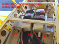
- Potenza 6S 6200mAh 40C batteries were used (Two in series (12S))
Battery Selection
- At the time of this writing, Flex Innovations has tested the KingTech K45 G3 and have found it to be a perfect match.
- The chosen motor uses the same bolt pattern and firewall hole locations as a DA Gas Engine making mounting easy.
- The Prop bolt pattern also matches the DA 4-bolt pattern.
- The Zicoy X45 is very similar, and its mounting was considered in the design. It should be easily fitted as well.
- Potenza 6S 6200mAh 40C batteries were used (Two in series (12S))
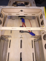
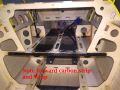
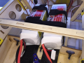
Reinforced the Battery Tray
Thin and medium CA Glue was used for all. See Images
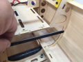
- Approximately 1/2 wide strips of Carbon plate (~.080" thick) was used in two places to reinforce the structure under the tray. It was wrapped to the structure with carbon chord (tow).
- At the aft end under the battery tray oriented vertically. Carbon chord wraps used.
- At the middle of the tray oriented flat against the bottom of the tray. Carbon chord wraps used.
- Two strips of Carbon plate were laminated to the top of the tray to stiffen it and to apply velcro® to.
- The aft edge of the plates were thinned to allow carbon chord wraps to be applied to prevent delamination.
- A hole were made in the front center of each plate, and the plated was wrapped to the existing structure with carbon chord to prevent delamination.
- Holes and slots were made in the tray to allow for carbon wraps, and velcro® straps

Motor and ESC
Tray Preparations
Tray Preparations
1 of 2 Carbon Strips
Strip in Middle
Aft Wraps
Overview

Aft Wraps
Middle Wraps
Middle Wraps
Radio Tray


